How to Switch Highly Inductive Loads Using Digital I/O
Application Example:
Highly inductive loads, those that use magnetic fields such as DC motors, produce a surge of voltage (referred to as “blowback voltage”) when a relay is opened, breaking power to the electrical circuit. This surge of blowback voltage is created by the collapsing of the armature coil’s magnetic field. In cases with large or higher wattage motors, this can cause an overvoltage condition on the motor and could cause the relay contacts to arc and possibly fuse. To protect against this overvoltage condition, care must be taken to dissipate the energy stored in the DC motor’s coil when power is removed and there is no longer a path for current to flow.
In this example, we will demonstrate why an open-collector output with a flyback diode is better suited for controlling applications that are considered highly inductive.
Application Explanation
Reed Relay Implementation
Figure 1 shows a simple circuit for controlling power to a 24V typical DC motor using a Reed relay on a Sealevel SeaI/O-440U distributed I/O module. For this example, we will use an oscilloscope to measure the voltage change when power is removed (turned off) using this circuit.
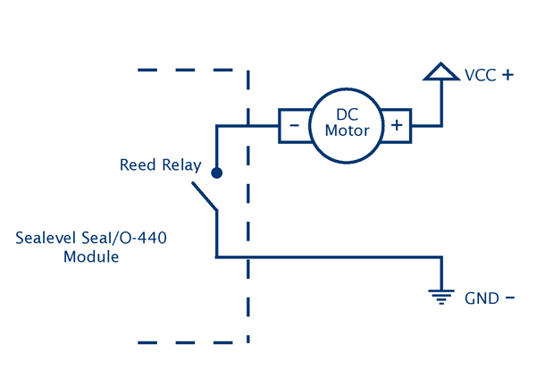
Figure 1
Figure 2 represents a graphic from an oscilloscope measurement of the voltage spike that is induced at the Reed relay terminals when the relay is opened, removing power from the DC motor. This graph shows a delta voltage (delta Y on the screen) of 127V. During testing there were approximately 200V (delta) spikes routinely observed when the Reed relay is turned from on to off, indicating that the Reed relay did not properly dissipate the highly inductive load energy from switching the DC motor’s power.

Figure 2
Open Collector Output
Figure 3 shows a circuit for a controlling a 24V DC motor with Sealevel’s SeaI/O-540U open-collector output module with integrated flyback diode controlling power:

Figure 3
Figure 4 shows a graphic using an oscilloscope measurement of the voltage change that is induced when power is removed from the DC motor when using an open-collector output from the SeaI/O-540 module. During the open-collector output testing, the largest observed voltage change was 30V DC at the output terminal.

Figure 4
Conclusion
When power is removed from a highly inductive DC motor, the motor’s blowback voltage must be properly dissipated to avoid damage to the electrical control circuit and/or the DC motor. This example clearly verifies that our open-collector output with a flyback diode circuit works very well at controlling highly inductive load energy associated with DC motors.
Sealevel’s SeaI/O-530 and SeaI/O-540 modules use open-collector outputs with integrated flyback protection diodes making them a good choice for this application. The flyback diode provides a path for current to flow and dissipate in these conditions.
If Reed relays are used for moderate inductive load applications, they may require employing circuit protection measures. Reed relays are perfectly suited for a broad range of control applications but are not typically called upon as a solution for highly inductive loads.
Equipment Specifications:
DC motor: Pittman/CPR: 500
Power supply: Bench top 24VDC
Oscilloscope: Rigol DS1052E
SeaIO-540U: (32) Open-Collector Outputs (each containing a flyback protection diode)
SeaIO-440U: (32) Form A – Reed Relay Outputs