Basics of RS-422 and RS-485 Communications
Q: I must create an instrument network but need some guidance on RS-422 and RS-485 communications. What’s the difference?
A: First, carefully describe what you want the network to achieve and then examine the physical-layer characteristics of each standard. Here “physical layer” refers to the signals on the bus or buses, signal timing, and connections between devices. After you decide how to create your network and which standard to apply, you can think about high-level protocols such as Profibus and Modbus, as well as others. RS-422 and RS-485 communications systems simply get bits from “here” to “there.” You decide how to use them.
The largest difference between RS-422 and RS-485 centers on the types of communications allowed. The RS-422 standard allows only one-way (simplex) communications between one driver, and as many as ten receiving devices. So if you plan to control devices and need no feedback from them, an RS-422 multidrop network will work well (Figure 1a). This bus needs only two wires for differential voltage signals. The word “drop” refers to a device on the bus.
Although the RS-422/V.11 standard does not allow multiple drivers on a 2-wire bus, you can create a 4-wire bus to enhance a multidrop RS-422 bus (Figure 1b). In this instance, the driver at the controller sends information to the slaves. If that information includes a request for information from a specific slave, it responds with status or other data. That slave-to-controller communication occurs on a separate pair of wires. You may include more than one slave device with a bus driver. But, such devices must have the internal capability to “disconnect” a driver from the bus. (Such a disconnection means the outputs switch into a high-impedance state and cannot affect the bus signals. Engineers call this a 3-state or tri-state device because it will produce a logic-0, a logic-1, or a high-impedance output condition.)
Not all slaves or driver/receiver ICs provide this type of control for driver outputs. The Texas Instruments SN65HVD179 driver/receiver, for example, has no way to disconnect its driver from a bus. On the other hand, a TI SN65HVD37 driver/receiver IC includes a control input that lets other circuits force it into the high-impedance state.
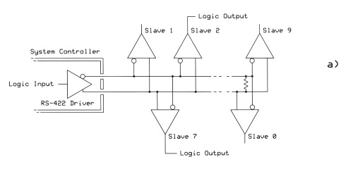
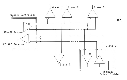
Figure 1. A simple 2-wire RS-422 network (a) includes only one driver and as many as ten receivers. The driver always maintains control of the bus. The slave devices cannot communicate with the driving device. When you must have responses from slave devices, use a 4-wire enhanced multidrop bus (b). Bus drivers in slave devices must have the capability to switch their outputs into a high-impedance state that “disconnects” from the bus. (For simplicity bus diagrams show parallel lines in place of the twisted pairs of wires used in practice.)
Q: Why can’t I connect more than ten slave devices on an RS-422 bus?
A: You can. The RS-422 standard specifies a maximum of ten 4000-ohm unit loads for bus receivers. Check manufacturers equipment specifications: newer devices might have a smaller load, say 1/4 or 1/8 of a unit load (UL). So in theory you could have forty 1/4-UL RS-422 devices on a single bus.
Q: So how does RS-485 differ from RS-422?
A: An RS-485 network allows as many as 32 drivers and 32 receivers. Some equipment and interface cards include an RS-485 driver and a receiver, while others might provide only a driver or only a receiver. Engineers refer to the RS-485 bus as a “party line” or “multidrop” arrangement because communications can occur between many devices. We use the term duplex to describe this type of back-and-forth communication. When your system requires a response from some devices or when more than one driver must communicate with various receivers, choose RS-485 products.
The RS-485 standard allows half-duplex and full-duplex communications. A half duplex arrangement connects all receivers and drivers to the same 2-wire bus as shown in Figure 2. In a full-duplex network, a driver can communicate with one or more devices and then another driver can use the bus to report results or send commands to other receivers. Figure 3 shows a portion of a full-duplex network that requires four wires for differential signaling.
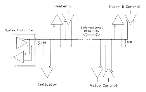
Figure 2. A half-duplex RS-485 network uses two conductors for communications between a controller and equipment. When commanded to reply with data, a slave device connects its driver to the bus and transmits bits to the controller at the left. In this network, the Indicator device has no need to reply.>

Figure 3. This full-duplex RS-485 arrangement provides for simultaneous 2-way communications. The System Controller’s driver transmits information to the slave devices on the upper bus. The slaves respond – one at a time – via the bottom bus.
Q: What’s differential about these signals?
A: Differential refers to a voltage difference created by a driver on the two signal lines. Unlike a single logic signal that varies between, say, 3.3 volts for a logic-1, and 0 volts for a logic-0, the two RS-422 and RS-485 signals change both their voltages. An RS-422 or RS-485 driver supplies two outputs, A and B, illustrated in Figure 4. When the driver receives a logic-1 signal at its input, VA > VB. For a logic-0 input, VA < VB. A driver must produce at least a 1.5-volt difference on the outputs. A receiver can detect a difference as small as 20 mV.
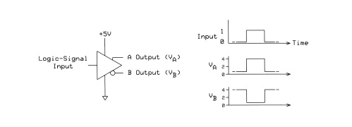
Figure 4. Voltage vs. time plots for the A and B outputs on a typical RS-422 differential driver. A logic-1 on the input forces VA to about 4 volts and VB to about 1 volt. A logic-0 input forces VA to 1 volt and VB to about 4 volts. The voltage difference always equals 3 volts, but the polarity, and thus current flow, reverses. An RS-422 driver produces the logic-1 output condition (VA > VB) when inactive. For oscilloscope diagrams of RS-422 electrical signals, refer to this article about serial electrical interfaces.
The use of differential signals improves immunity to electromagnetic interference (EMI) because any noise induced on one of the differential signals also affects the other equally. The voltage difference remains the same. The use of twisted-pair wire also helps reduce effects of EMI on RS-422 and RS-485 signals.
Q: The RS-422 and RS-485 differential signals have the same characteristics, so can I mix RS-422 and RS-485 devices on a bus?
A: We say that RS-485 devices are “backward compatible” with RS-422 networks. That means you can add an RS-485 receiver to an RS-422 bus, but you cannot put an RS-485 driver on an RS-422 bus that already has a driver. Many RS-422 drivers always maintain control of the bus, which means they always produce voltages on their outputs. The presence of these signals would cause conflict with outputs from an RS-485 driver. For the same reason, never put an RS-422 driver on an RS-485 bus.