Control System Basics – NPN vs. PNP Logic
In the third installment of this five-part series, Jon Titus explores the basic elements of a control system. In the first two installments, Jon covered relays and sink vs. source control.
NPN vs. PNP
Q: Now I understand relays and current sinks and sources. Some of the sensors I plan to use come in two varieties, PNP and NPN. What do these abbreviations mean and what are the differences between NPN vs. PNP?
A: The initials indicate a type of transistor used in the output section of many sensors. Before discussing sensors and controller outputs, a short explanation of both transistor types will get you off to a good start without the need for a degree in semiconductor physics! (The Ps and Ns refer to types of semiconductor material.)
NPN and PNP transistors each have three leads, a collector, a base, and an emitter, as shown in Figure 9. In circuit diagrams, the emitter always appears as an arrow. The arrow points out for an NPN transistor and in for a PNP transistor. The arrow’s direction identifies the transistor type in data sheets and schematic diagrams.
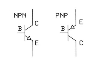
Figure 9. Schematic-diagram symbols for an NPN and a PNP transistor.
Both transistor types operate as current devices, so think of them as valves for current flow. The transistor base connection controls the amount of current that flows. Figure 10 shows a circuit for a common NPN-transistor that connects to an LED. In this circuit, current will flow from the positive supply through the LED into the collector and then out the emitter to ground. When a small current flows into the base the transistor starts to conduct a larger current from the collector through to the emitter and then to ground. The combined base and collector currents flow out the emitter terminal. Small changes in base current cause larger changes in the collector-to-emitter current.
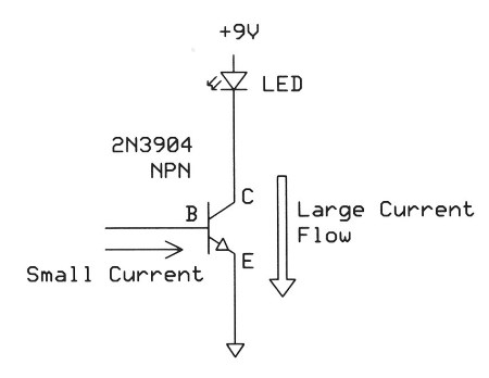
Figure 10. An NPN transistor controls current flow through an LED. A small current into the base turns on the transistor just a bit. A higher current into the base lets a higher current flow and the LED becomes brighter. Think of this circuit as a current sink because the LED connects directly to the higher potential and the transistor connects directly to ground.
PNP transistors work in a similar way: The base current still determines how much current flows from the emitter to the collector. But in PNP transistors the control current flows out of the base rather than into it. Figure 11 shows an LED-control circuit with a PNP transistor. To control the LED brightness we draw current from the transistor base. (The current goes to ground.) A small current out of the base causes a larger current to flow from the emitter to the collector.
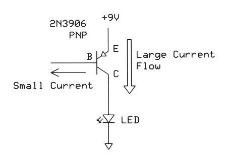
Figure 11. This circuit shows how current drawn from a PNP transistor base controls the flow of current from the emitter to the collector. This circuit is equivalent to a current-source because it controls the flow of current from the highest potential to the load that connects directly to ground.
This type of current “amplification” finds use in many sensors. In a Hall-effect position sensor or an ultrasonic distance sensor, for example, sensitive circuits detect a magnetic field or a distance. The measurement circuits do not directly send a high-current signal (a few 10s of milliamperes) to a controller. Instead, manufacturers include an NPN or a PNP transistor to handle higher currents at a sensor’s output. You must ensure that sensors with PNP outputs connect to PNP-compatible controller inputs and NPN outputs connect to NPN-compatible inputs.
As a memory tool, think about the PNP transistor as a direct switch connected to the Positive voltage supply and the NPN transistor as a direct switch connected to the Negative (ground) voltage.
The two circuits in Figure 12 illustrate the connections for an NPN and a PNP sensor’s connections to a compatible controller and its internal “detector.” The Hall-effect sensor could report an on-or-off condition and the ultrasonic sensor could produce a current proportional to distance. The “detector” would take action based on the current it receives. Some people prefer the NPN format because it always provides a connection to ground, or zero volts, whereas a PNP sensor could have a wide range of voltages on their outputs, depending on the sensor’s manufacturer and its design.

Figure 12. These diagrams show how current flows in an NPN and a PNP sensor connected to a compatible controller. Compare these circuits with the LED-control circuits in Figures 10 and 11.
Q: I understand how a PNP sensor sources current and how an NPN sensor sinks current. In my equipment, some sensors will control relays and other sensors must supply logic levels to equipment. Will the PNP and NPN connections still work?
A: Yes, but you have two different situations; direct control of an on-or-off device or the need to produce two voltages to represent a logic-0 and a logic-1. Let’s look at both. You can use a simple current sink or current source to control a relay coil, for example, because it either gets current or it doesn’t. The flow of current through the coil can go in either direction. (Note: You want relays specified for a DC coil current. Relays that use an AC coil current differ in construction and might not be suitable for a DC coil current.)
On the other hand, logic devices require two voltages, each within a specific voltage range. These voltages depend on the logic family in use. For a chart of logic-level voltage ranges, please visit: http://www.interfacebus.com/voltage_threshold.html.
So how do we use an NPN current sink or a PNP current source to provide two voltages? The solution requires an external resistor, although some manufacturers might include an optional resistance in equipment. Assume our situation involves standard 5-volt TTL signals, so a valid logic-0 signal must have a voltage between ground (0.0V) and 1.3V. A valid logic-1 signal has a voltage between 3.7 and 5.0V.
An NPN current sink makes a connection to ground, or 0 volts. That suffices for a logic-0 signal. By adding a pull-up resistor to the NPN open-collector, this pin produces a logic-1 voltage when the NPN transistor turns off. When you have a PNP open-collector connection, it will provide the supply voltage for a logic-1 but it requires a pull-down resistance to produce a valid logic-0 when the transistor turns off. Figure 13 illustrates both situations.
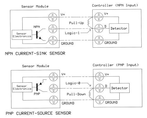
Figure 13. When the PNP and NPN transistors turn off (shown as disconnected here), no current flows to or from the Detector so we don’t know for sure what voltage–if any–the detector input “sees.” An added pull-up or a pull-down resistor supplies the proper logic level when transistors turn off. Each input requires its own resistor.
Note that the resistor in the NPN situation connects to the V+ contact on the Controller. For the TTL signals used as an example, V+ must connect to +5V. But you might not have that voltage available. In that case, provide an external +5V power supply and use it with the resistor (Figure 14). Ensure the positive voltage used with your pull-up resistors always matches the V+ specified for the logic family in use.
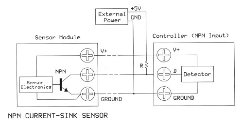
Figure 14. An example of a pull-up resistor and a separate 5-volt power supply used with an NPN current sink to produce logic levels independent of the power-supply voltage in the controller or the sensor. The 5-volt power-supply ground must connect to the ground between the sensor and the controller.
Often a controller with open-collector outputs must control external devices. In this situation, the controller provides a current or logic level. Figure 15a illustrates the situation in which the device requires a logic level between V+ and ground from either an NPN- or a PNP-type output. Figure 15b shows the use of an NPN- and a PNP-type output when a device such as a relay coil requires only an on-off current flow. Whenever you use an NPN or PNP output to control a device, check the output specification. The open-collector outputs on a SeaI/O-530E module, for example, can handle DC voltages as high as 60V with a maximum current of 1000 mA (a combined total of 2000 mA for all open-collector outputs in a module).
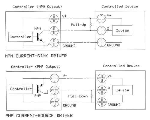
Figure 15a. A controller or I/O module may offer either NPN or PNP outputs. In these circuits, the controller supplies a logic level of either ground or V+ to the controlled device.

Figure 15b. The NPN or PNP outputs also may serve as current sinks or sources that require no pull-up resistors. Here the open-collector outputs control on-off current through a relay coil.