Control System Basics – Relays Explained
In the first installment of this five-part series, Jon Titus explores the basic elements of a control system. Check back next month for the 2nd installment.
Q: I just started to design a control system and plan to use relays to turn devices on or off. Relay-module specifications note “C relays” and NO and NC contacts. Can you help me understand what this information means?
A: A relay comprises an electromagnet, or coil, and a set of electrical contacts. Figure 1 illustrates the relay parts. When a circuit energizes the coil, the armature moves toward the coil and “breaks” its connection with the upper contact and then “makes” a new connection with the bottom contact. Construction does not allow any electrical path between the contacts and the current that controls the coil. In this way the control circuit remains electrically isolated from a device that the relay contacts turn on or off.

Figure 1. Component parts of an electromechanical relay. The spring causes the armature to move away from the coil unless a circuit has powered it. This diagram shows an open-frame relay. Relays used in industrial equipment often come in sealed enclosures to keep contacts free of dust and other contaminants. (Courtesy of Wikimedia Commons)
The letters “NO” and “NC” refer to the state of the contacts when the coil is un-energized. NO stands for normally open, and NC stands for normally closed. In Figure 1, the armature would let current pass through the upper, or normally-closed (NC), contact. The bottom contact remains unconnected to the armature, or normally open (NO) until power goes through the coil. The armature usually has the designation “C,” for “common.” This relay designation can get a bit confusing and you’ll soon learn why.
Relays come in a variety of styles, from large relays with high-current contacts that control motors, to small reed relays that systems employ for low-voltage, low-current signals. Reed relays are particularly useful when you must switch analog signals from sensors and connect them to a digital voltmeter (DVM) or an analog-to-digital converter (ADC).
If you want to power a motor (M), when a relay closes you would wire it as shown in Figure 2. In this example a green light would turn on when the relay contacts go back to the NO position, which means the coil no longer receives current. The green light might indicate the motor is off. Energize the coil and the green light turns off and the motor runs.

Figure 2. A circuit that uses a relay to switch power to a light (relay un-energized) or to a motor (relay energized).
Q: OK, I understand the labels for relay contacts. Why does the letter C cause confusion?
A: You now know “C” refers to the common relay contact, the armature. But the electrical industry also uses letters to define the arrangement, or “form,” of relay contacts (Figure 3). A form-A relay has a single NO contact, and a form-B relay has a single NC contact. These are both single-pole single-throw (SPST) relays. They each either open or close one set of contacts (single pole), and they each have only one state that closes or opens a circuit (single throw).
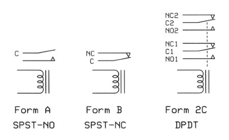
Figure 3. Contact arrangements for several types of electromechanical relays. The dashed lines in the form-2C relay indicate both armatures have a non-conductive link that moves both simultaneously when the relay coil receives current.
The relay shown earlier in Figure 2 has an NO and an NC contact; the form-C arrangement. We also call this a single-pole, double-throw (SPDT) arrangement of contacts. In Figure 3 you see a form-2C relay also called a double pole, double-throw (DPDT) relay.
Q: If one of my controller boxes includes form-1C or form-2C relays, how do I use them to control something?
A: You connect the device as shown earlier in Figure 2. A SeaI/O module, such as a SeaI/O-420E, with form-C contacts would get wired as shown in Figure 4. The screw terminals make electrical connections between four loads and the relay contacts. In this case we must supply a current source for the loads. The SeaI/O module does not. It only controls the relay coil. How we use the relay contacts is up to us. The diagram includes the maximum AC and DC voltages and power for the relay contacts. Relay specifications include information about the voltage needed to actuate an armature, the current the coil draws (or its resistance), as well as the maximum ratings for the relay contacts for both DC and AC loads.

Figure 4. Diagram for wiring a Sealevel Systems SeaI/O-450U USB Data Acquisition Module. A design must include an external power source for controlled devices. The relay contacts have no connection with the module’s internal circuits. You get complete electrical isolation. The SeaI/O-420E provides eight form-C relays in four groups, or banks, of two relays each. Each pair of relays have a shared common signal.
The example illustrated in Figure 4 provides only one common connection which means the armatures of the #1 and #2 sets of contacts connect to the same electrical point. Other configurations could offer a separate common connection for each set of contacts. Figure 5 shows this common connection.
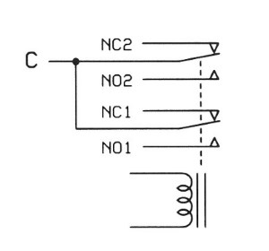
Figure 5. The terminal block in Figure 4 shows one connection for the armatures in the #1 and #2 sets of contacts. The circuit shown here illustrates that common connection.
We hope you enjoyed the first installment. Check back next month where Jon will explain Sink vs. Source Control in his Control System Basics series.