How to Properly Configure and Wire RS-422 and RS-485 Networks
Q: Why do the diagrams for the RS-422 and RS-485 buses include resistors at the end of the bus wires and what values do I need for them?
A: Signals that reflect from the end of an unterminated bus with a high-enough amplitude can cause problems for other devices that see these reflections as real communications. Proper termination of the bus with a pure resistance that matches the wire’s impedance attenuates reflections. The terminations are placed at the driver and receiver farthest from each other. A device with an RS-485 or RS-422 port might include a built-in termination resistance you can connect to a bus if needed or leave disconnected. Use only two terminating resistors!
Typically, twisted pair wire has an impedance of about 120 ohms, so we use 120-ohm resistors at the ends on the longest cable runs. Keep in mind the longest run might not be a straight line. You must measure all the lines in your network to determine the longest path. Remember that a full-duplex RS-485 network requires termination resistors on both buses.
Q: Some diagrams of an RS-485 bus show other resistors on the bus that connect to the positive power source and to ground. What do they do and should I include them?
A: In an RS-422 network, the lone driver always produces a logic-1 or a logic-0 output. It never disconnects electrically from the receivers. So bus receivers always “see” a valid logic level, even when no bus activity occurs.
An RS-485 bus can include more than one driver, so when a driver does not transmit, circuits internal to the instrument or controller “disconnect” the driver signals from the bus. Then other drivers may use the bus. The outputs of a disconnected driver go into what we call a three-state mode; essentially a high-impedance mode that will not affect the bus. Three state modes comprise logic-0, logic-1, and high-impedance conditions.
What happens if all drivers go into the three-state mode? What signals appear on the bus? We don’t know. To ensure receivers don’t detect the high-impedance state as erroneous data, bus designs may include a pull-up resistor for the driver’s “A” output (Data-Out +) and a pull-down resistor for the driver’s “B” output (Data-Out -) as diagrammed in Figure 5. Some driver integrated circuits include a fail-safe circuit that places a three-state bus in a known state to prevent errors at receiver inputs. Check with equipment manufacturers about the need for the “bus-bias” resistors.
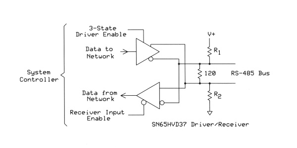
Figure 5. An example of a pull-up and a pull-down resistor on an RS-485 bus to ensure the proper voltages on an inactive bus. The Texas Instruments SN65HVD37 IC used in this example includes a 3-state enable input to force the two driver outputs into a high-impedance state. The receiver also includes an enable signal equipment manufacturers could use to “turn off” the receiver.
Q: How long can I run a cable for RS-422 or RS-485 communications?
A: It depends. Manufacturers of equipment with RS-422 and RS-485 interfaces note a maximum of 4000 feet (1200m), but the higher the communication frequency, the shorter the maximum cable length. Several sources provide a log-log plot of cable length vs. data rate. The 4000-foot length holds until a data rate of about 90 kbits/sec. Then the rate decreases along a straight line to about 10 Mbits/sec for a 15-foot bus length. For an example plot, see: Marais, Hein, “RS-485/RS-422 Circuit Implementation Guide,” Application Note AN-960, Analog Devices. http://www.analog.com/media/en/technical-documentation/application-notes/AN-960.pdf.
Most practical buses include “stubs” that connect equipment off the “main bus.” According to a Texas Instruments Application Report, “…the electrical length of a stub should be shorter than 1/10th of the driver output rise time.” The following equation gives you the variables and values for a L19954 Series cable from Automation Direct (www.AutomationDirect.com). This cable has a signal velocity of 0.662 times the speed of light, and an impedance of 120 ohms. A Texas Instruments SN65HVD12 bus driver, for example, has a 100 nsec rise time at a transmission speed of 1 Mbit/sec.
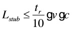
Lstub = stub length in feet
tr = driver rise rime in nsec (10% to 90%)
v = wire signal velocity as a fraction of c
c = speed of light in ft/sec (982 x 106)

So in this case, a stub from the main bus can have a length of 6.5 feet or 2 meters.
For more information about bus-length considerations and calculations, please refer to:
1. Kugelstadt, Thomas, “The RS-485 Design Guide,” Application Report SLLA272B, Texas Instruments, May 2008. http://www.ti.com/lit/an/slla272b/slla272b.pdf.
2. Gingerich, Kevin, “Device Spacing on RS-484 Buses,” Analog Applications Journal, Texas Instruments, 2Q 2006. http://www.ti.com/lit/an/slyt241/slyt241.pdf.
Q: I have a lot of new CAT5e and some CAT6 cable. Could I use it in an RS-422 or RS-485 network?
A: Short answer; yes. You don’t need CAT6, which handles 10 Gbits/sec Ethernet. It doesn’t pay to spend money for capabilities you won’t use. The CAT5e cable works well when you choose the proper pairs: blue and white-blue, green and white-green, brown and white-brown, or orange and white orange. In a sample of cable in my lab I found three twists per inch. If you choose, say, brown and orange instead of a twisted pair, you decrease immunity to EMI.
Q: Should I use shielded cable?
A: A shield around the twisted pairs also helps reduce or eliminate problems caused by EMI. If you choose a cable with shielding, connect the shield to ground only at one end. Never use a shield as a return-ground path that carries current. Instead, use a cable that includes a separate conductor for a ground return.
Q: Do RS-422 or RS-485 always need a ground return?
A: Yes, RS-422 and RS-485 always need a common-ground reference for proper communications. Although receivers detect differential signals, equipment needs a ground return path to keep signals within the common mode range of the receivers. Common mode refers to an equal voltage added to the bus signals. Without a ground return, the voltage difference between the two bus signals may exceed the receiver’s maximum common-mode rating. A Maxim Integrated MAX14891E bus-receiver IC has a maximum ±20 volts. If the common-mode voltage exceeds this value you will see data errors or perhaps damage the receiver. Even though the RS-422 and RS-485 signals are sent differentially, a network still needs a ground return path.
That said, though, a communication system probably has a common ground provided through the mains-power grounds at various locations. Often we forget about these ground connections in common with our instruments and measurement devices. These connections often form a ground loop caused by different ground potentials in the loop (Figure 6). Ground loops can offset voltages between distant devices and even induce signals on the network at mains-power frequencies. If ground loops become a problem you can use isolation circuits or device to break the loop. The Sealevel Systems SeaLINK® 2113, for example, provides a single-port RS-232, RS-422, or RS-485 serial interface that isolates the bus signals from a host PC. The PC connects to this module via a USB port.


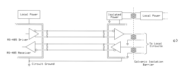
Figure 6. The first circuit (a) illustrates how a ground loop can occur in equipment with a common ground. The power equipment ground can experience large voltage differences at many points. The second circuit (b) shows a technique that helps reduce ground currents and thus decreases the voltage difference between the two network devices. Electrical isolation (c) provides the best way to eliminate ground loops, but at extra cost. The galvanic separation–represented here by transformers–isolates a remote device from ground loops.
Q: What can I do if I need more than 32 devices on an RS-485 bus?
A: The input impedance of 32 receivers on a bus creates a limit for proper bus operation. Each standard RS-485 receiver has an input impedance of at least 12 kohms, which has the designation one unit load (UL). You can buy equipment that appears to the bus as a 1/4 UL or a 1/8 UL. Eight of the 1/8 UL receivers can connect to the bus in place of one 1 UL device. So you can connect more than 32 receivers.
Q: Some communication networks allow for star, tree, ring, and other network topologies or layouts. Can I use them with RS-485 devices?
A: Your best results come from a linear (straight-line) bus with stubs that connect equipment. People might refer to this as a “backbone” topology. If you create a star network, for example, you end up only with stubs that will cause problems. The simpler the topology, the fewer the problems. Of course you must comply with the length limits for a linear bus at a given data frequency, as well as length limits and separation distances for stubs.