
Control System Basics – Sink vs. Source Control
In the second installment of this five-part series, Jon Titus explores the basic elements of a control system. Click the following link if you missed the first installment: Relays Explained. Check back next month for the 3rd installment.
Q: OK, the relays and their operations seem clear. In a few cases, I’ll use an off-the-shelf controller’s outputs to turn a device such as a solenoid on or off. But many controllers have either current-sink or current-source terminals rather than relay terminals. What do these labels mean and how do I use them?
A: Let’s look at a simple circuit with a battery and a light bulb (Figure 6). When we provide a complete circuit path, by convention current always flows from a higher to a lower voltage. In this example, current flows from the battery’s positive terminal through the bulb and to the negative terminal. Thus, the more-positive terminal provides a current source, and the more-negative terminal provides a current sink.
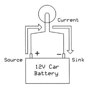
Figure 6. Every electrical circuit must have a path between a high and a low potential for current to flow. The positive battery terminal acts as the source and the negative terminal acts as the sink.
A controller module with current-source output terminals will turn on or off a current to a device that already has a direct connection to ground. An internal switch controls the current-source connection via commands from a PC or other module. Figure 7 shows a current-source arrangement. Commercial devices with current-source outputs often require a separate power supply, shown as a battery in this example. A device with current-source outputs always has a maximum voltage and current specification.

Figure 7. Current-source connections typical of those on an industrial-control module. This module requires an external power supply for the sources. Shown here as a battery symbol. In this example, the Source C output supplies current to the Alarm device to turn it on. The Green Lamp is not energized. An arrow shows the current-flow path.
Of course, equipment may provide current-sink inputs instead of sources, but the principle is the same–current flows from a high potential to a low potential. In the case of current sinks, the devices you want to control must have a connection to a positive voltage. When a sink input turns on, current flows into the sink and completes the circuit to ground. Figure 8 illustrates connections for current-sink switching. Compare the current flow in Figures 7 and 8 and look at the battery connection on the right-hand side of each switch.
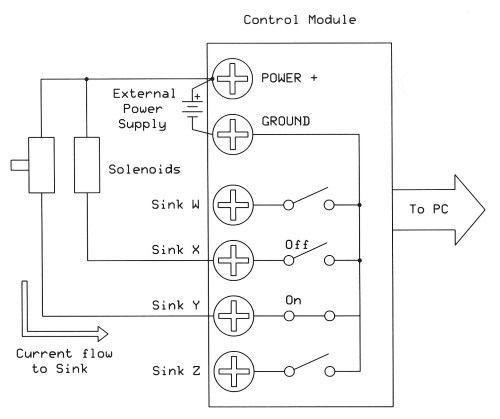
Figure 8. A set of current-sink switches connects powered devices to ground and completes a circuit to turn them on. In this case, all devices connect to the power supply’s positive-voltage screw. The Control Module makes the connection to ground based on commands from a PC or other controller. An arrow shows the current-flow path.
We hope you enjoyed the second installment. Check back next month where Jon will explain PNP vs. NPN Logic in his Control System Basics series. Be sure to read the first installment:
Categories: