The Digital I/O Handbook – Chapter 3
The Digital I/O Handbook
A Practical Guide to Industrial Input & Output Applications
Digital I/O Explained
Renowned technical author Jon Titus and the President and CEO of Sealevel Systems, Tom O’Hanlan, clearly explain real-world digital input/output implementation from both a hardware and software perspective. Whether you are a practicing engineer or a student, The Digital I/O Handbook will provide helpful insight you will use again and again.
- Covers a wide range of devices including optically isolated inputs, relays, and sensors
- Shows many helpful circuit diagrams and drawings
- Includes software code examples
- Presents common problems and solutions
- Detailed glossary of common industry terms
“What I like most is its mix of hardware and software. Most pages have a bit of code plus a schematic. All code snippets are in C. This is a great introduction to the tough subject of tying a computer to the real world. It’s the sort of quick-start of real value to people with no experience in the field.” – Jack Ganssle, The Embedded Muse, January, 2005.
You can purchase the Digital I/O Handbook for $19.95 by clicking here. The Digital I/O Handbook is FREE with any qualifying Sealevel Digital I/O product purchase.
Chapter 3 – Digital Inputs
Topics Covered
- Introduction to input ports
- Basic TTL inputs
- Circuit isolation
- Current sinks and sources
- LED considerations
- Monitor high voltages
- Sense bits with software
- Flags
- Put it all together
- A final note about I/O ports
Introduction to input ports
Few computers can operate without connections to external devices such as sensors, switches, or other equipment that informs software about external conditions. Computers also receive data from keyboards, disk drives, touchscreens, and similar devices, all of which transfer their information to a computer through a device called an input port.
You can think of many practical uses for input ports. Imagine a controller that counts parts on a conveyor belt. An electronic counter in the controller would provide data that a computer could obtain from an input port. Similarly, an input port connected to a digital thermometer would let a computer read temperature values at any time. The computer simply retrieves the specified data as requested by a software command.
At its simplest, an input port acts like a “gate” that lets information pass from an external device to a computers data bus at a specific time. The central processing unit (CPU), or its control circuits, provide a unique strobe pulse for each input port. That pulse “tells” a port when to transfer data onto the data bus so the CPU can
capture it. To control the transfer of data from an input port to the computer, the computer requires a port-control command that identifies a specific port. Only one device can use the bus at a time.
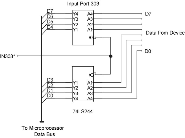
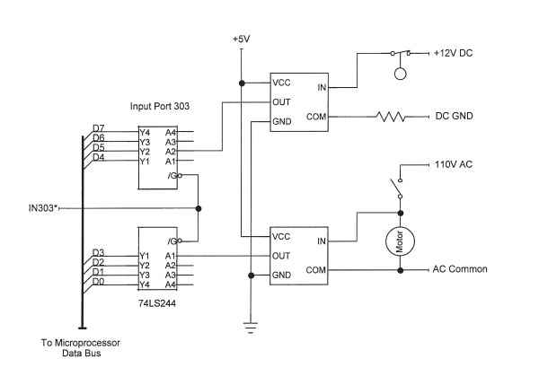
Figure 3-1 shows a typical input port. Any information present at the ports eight inputs gets transferred to the CPU when the strobe pulse, IN303*, arrives. The single 74LS244 IC used in the example contains two independent 4-bit circuits. Weve used them to form a complete 8-bit input port. Other TTL devices work equally well. (Our port-number assignments carry no significance and simply serve as examples. You can use port numbers within the ranges specified for the computer and software you plan to use. Some computers reserve I/O port numbers for internal and future use.)
The input port shown in Figure 3-1 might accept signals from on-off switches or other devices that produce TTL-compatible signals. As always, the external signals, the input-port circuits, and the computer must share a common ground.
Figure 3-1
A simple 8-bit input port places information on the bus only when the computer places a short logic-0 pulse on the IN303* line. At other
times, the port “disconnects” from the bus using three-state logic.
To avoid conflicts on the CPU bus, input ports must “connect” themselves to the CPU data bus only when they receive the proper strobe pulse. At all other times, they must “disconnect” from the bus. The disconnect operation requires special gates with three-state outputs. These gates provide the normal logic-1 and logic-0 outputs, and they also provide a disconnected or third state. In this state, they appear electrically disconnected from the data bus. You may hear designers refer to similar devices called three-state bus drivers or three-state buffers. These devices provide the capability to disconnect outputs from a bus or other conductor that carries signals from several sources.
Transfer of data from an external device through an input port to a computer requires a software command. This command causes the computer to generate the needed strobe pulse at the input port so that the port data flows onto the bus:
portdata = inportb(input_port_number)
The general command above addresses a specific port (input_port_number) and assigns the data from the port to a variable, in this case, portdata.
The following command would obtain data from the port shown earlier in Figure 3-1:
abcxyz = inportb(303)
Software examples in this chapter illustrate byte transfers, and they assume, unless shown otherwise, that a programmer has defined variables, such as input_port_number, portdata, and abcxyz to hold values. After acquiring the data from an input port, additional software commands can use the information to make decisions.
In essence, an input port takes a “snapshot” of the information present at the port when the ports strobe pulse arrives from the CPU. The computer does not wait for data to arrive at the port from an external device; it simply says to the input port, “Give me what you have now.”
The inportb command shown above does not exist within some programming languages such as Visual Basic. Each manufacturer of add-in cards or devices supplies its own driver software. Drivers come in a library of routines that link a programming language to special operations, such as those that control I/O ports. Thus, drivers define new commands that a programmer can include in code to transfer data from an input port to a CPU.
You must follow instructions included with an I/O board to properly set up accompanying driver software. The setup process lets your application program know how to find and use the drivers on the computer hard drive. (The instructions that accompany a board and its drivers provide installation information and information about how to use drivers in your application program.)
Basic TTL inputs
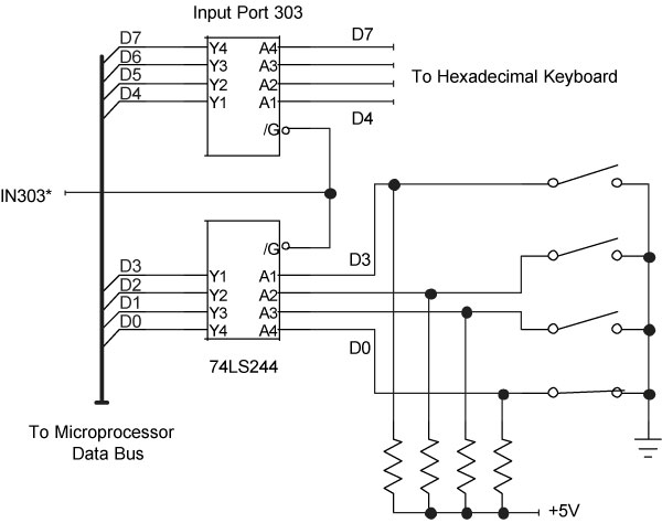
An 8-bit input port can obtain information from on-off switches, encoded switches, sensors, keyboards, and other devices that produce TTL-compatible signals. As with output ports, you can use the input bits in any way you wish, perhaps using four input bits to get data from a hexadecimal keypad, and the remaining four bits for on-off switches, as shown in Figure 3-2.
Figure 3-2
An input port can accept data from many sources, such as individual switches and a hexadecimal keyboard. These external devices provide
TTL-compatible logic signals and a common ground to the computer.
CAUTION: Digital signals drawn in books often look perfect, but real-world signals usually include some noise and may not meet the electrical specifications for logic-1 and logic-0 signals in a given logic family. So, external digital signals may require some conditioning prior to connecting them to the TTL-compatible inputs at an input port.
You can use a Schmitt trigger circuit, available in most TTL families, to provide some signal conditioning. But first check the specifications for all input ports you plan to use. Some ports may come with built-in Schmitt triggers.
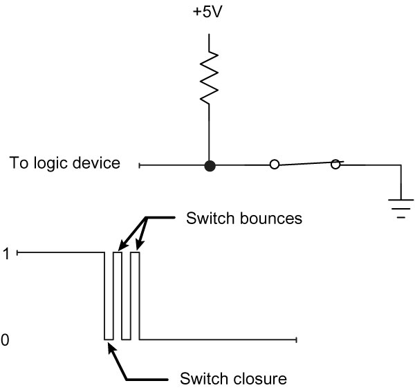
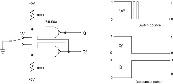
CAUTION: If you plan to connect simple on-off switches or pushbuttons to an input port, you may need to “debounce” the switch contacts. When a pair of mechanical contacts closes, they have a tendency to bounce for a short time. While doing so, the contacts may open several times as shown in Figure 3-3 for a closing SPST switch. Although these bounces end within a few milliseconds, circuits may detect them as several switch closures in rapid succession. In a double-throw switch, the movable contact DOES NOT bounce back and forth between the two stationary contacts; it simply opens and closes the connection at the contact it was switched to.
Figure 3-3
If a mechanical switch bounces momentarily, an attached logic circuit may see each bounce as a logic transition.
If necessary, you can build a switch-debounce circuit using a single-pole double-throw (SPDT) switch or pushbutton, a pair of NAND gates, and two resistors, as shown in Figure 3-4. As soon as the movable contact in the switch touches a NAND gate input, the circuit changes its state and remains in that state until the movable contact touches the other fixed switch contact.
Figure 3-4
Two NAND gates form a switch-debounce circuit that offers complementary outputs, Q and Q*.
Because the debounce circuit produces two complementary outputs, one from each NAND gate, you can choose whether you want a logic 1 or a logic 0 to represent the normal output of the switch. Remember, the NAND gate circuit and any circuit it connects to, such as an input port, must share a common ground.
Circuit isolation
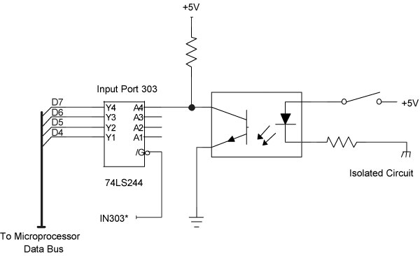
Although some sensors, instruments, and other devices produce TTL-compatible signals that can directly connect to an input port, many devices do not. You can convert these non-TTL-compatible signals into TTL levels, or you can buy input-port cards that provide the proper “translation” circuits. The easiest and most flexible translation involves using optical isolators, and many input-port boards and modules include these devices. At an input port, the phototransistor connects to the input ports TTL inputs as shown in Figure 3-5. An external circuit powers the light-emitting diode (LED).
Figure 3-5
An optical isolator IC electrically isolates an external circuit from the signals at an input port. This example shows only one bit, and for clarity, the input port shows only bits for D7D4.
Because the LED offers no direct electrical connection to the input port, it isolates the port (and the computer it connects to) from external devices. Thus, an external circuit can power the LED without regard to specific TTL levels and without a ground in common with the port and the computer. But the external circuit must supply a voltage and current within a specified range to properly operate the LED. Specifications that accompany an optically isolated input-port board or module will help you determine the maximum voltage and current an LED can accept. Because LEDs operate based on current flow, they are less susceptible to noise than standard TTL-compatible inputs.
Some optical isolators provide two “head-to-tail” LEDs in parallel. This arrangement lets you use low-voltage AC or DC to power the LEDs, regardless of the direction of current flow. Remember, LEDs act as diodes, so they allow current flow in only one direction. When an optical isolator requires a signal with a specific polarity (current-flow direction), the power source must match the required polarity.
CAUTION: DO NOT use small AC optical isolators to detect high-voltage signals, such as those in power-line (120V AC or 220V AC) circuits. Special devices can monitor signals at these voltages. Prior to use, always check suppliers specifications for LED voltage and current limits.
If you have difficulty getting an optically isolated input port to operate properly:
- Ensure the circuit properly matches the polarity of the external circuitry and the polarity of the optical isolator.
- Ensure you have a complete circuit to drive the LED.
- Ensure the LED-drive circuit will deliver more than the minimum voltage and current needed to turn the LED on.
Current sinks and sources
Not all devices that connect to a computer provide TTL signals or mechanical switch contacts. A sensor may offer an output labeled as a current sink or current source, terms that may confuse users and lead to nonworking interface circuits. To further confuse the issue, some manufacturers use the term NPN sensor for a current sink, and PNP sensor for a current source. The designations NPN and PNP simply refer to the type of transistor the sensor uses as its on-off switch. The circuits in Figure 3-6 show how NPN and PNP sensor outputs can control optically isolated input ports and TTL-compatible inputs.
Figure 3-6
Sensors that furnish NPN or PNP transistors on their outputs can power optical isolators. The bottom diagram shows a circuit in which designers supplied an external power supply.
This nomenclature can get confusing, so heres a way to keep the PNP and NPN designations straight. Think of the first letter in each abbreviation. A PNP device supplies power from the most Positive side of a circuit. On the other hand, an NPN device sinks current to the most Negative side of a circuit. NPN and PNP sensors operate only with DC power.
If you have a sensor that supplies a current-sink, or NPN output, the sensor provides an on-off switch to ground. An external circuit –
sometimes included by the sensor manufacturer provides the current and voltage to drive an LED in an optical isolator. So, you can choose just about any available power source, say, 5V, 12V, 24V, and so on, depending on what power sources your system already includes. Or you can add an external power supply. The manufacturer of the optically isolated input port should include information about the minimum voltage and current specifications for optical isolators.
A sensor that provides a current source, or PNP, output usually provides a connection to a power supply. Unfortunately, you may not have a choice in the selection of the voltage this current source operates from. So, you must ensure that the sensors current capability and output voltage are within the limits specified by the input-port supplier.
LED considerations
All LED circuits require a resistor that controls the current through the LED. Many manufacturers of optically isolated input-port boards and modules include a resistor for each input-port bit. Some boards and modules will require an external user-supplied resistor. Check the manufacturers specifications for details. Also, always ensure the voltage you plan to use at an input port meet the board manufacturers specifications.
Whether a board provides a resistor or requires an external one, simple calculations will determine the needed resistance value for a given voltage. Heres an example for the Sealevel Systems M240 Optically Isolated Input Adapter. Each of the eight inputs on the board has the same specifications:
Turn-on current (minimum): | 3 mA (0.003 A) |
Diode voltage drop: | 1.1 V |
Maximum resistor power: | 1 W |
turn-on voltage = (diode voltage drop) + [(turn-on current) * (resistance)]
So, if a sensor provides a 12V DC source, calculate the needed resistance for a 3 mA current flow:
(turn-on voltage) - (diode voltage drop) | = Resistance |
(Turn-on current) |
12 - 1.1 | = 3633 ohms |
0.003 |
The M240 board provides a built-in 3300W (1W) resistor that will work fine. (To ensure operation of the isolator, you can increase the current slightly. The optical coupler on the M240 board, for example, can handle a maximum LED drive current of up to 50 mA.)
Monitor high voltages
The small optical isolators furnished at input ports on commercial modules or boards will work with many types of sensors and data sources. But some applications require input ports that can monitor high voltages such as those that control pumps, solenoids, valves, and other devices. In this type of situation, designers rely on commercial plug-in modules specifically designed to offer optical isolation and to operate with high-voltage AC and DC signals.
Manufacturers of the output modules described in Chapter 2 also supply input modules that produce a TTL-compatible signal that indicates the presence or absence of a voltage on a corresponding input. LEDs on the modules indicate the state of each input.
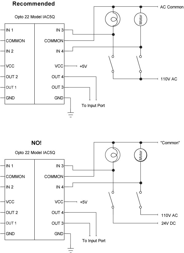
The 1781-IA5Q module from Western Reserve Controls (www.wrcakron.com) or the IAC5Q module from Opto 22 (www.opto22.com) provides four circuits that monitor AC or DC signals between 90V and 140V. A module includes two pairs of input circuits and the two circuits in a pair share a common connection. If you need to monitor two devices that operate from the same 110V AC power source, and the devices share a common ground, the diagram in Figure 3-7 illustrates typical connections.
Figure 3-7
An optically isolated input module provides two pairs of separate circuits (right and left). Do not mix AC and DC signals in one section of a module, and do not mix signals that do not share a common connection.
But within a pair of inputs, you cannot mix circuits that do not share a common ground. Also DO NOT mix AC and DC signals in a pair. Separate pairs of circuits can handle AC and DC signals within a module, though. The sensing circuits in these two models produce a logic 0 when they detect a voltage within the manufacturers specified limits.
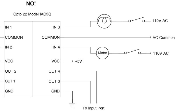
CAUTION: Always use an input module in parallel with a device; NEVER place a modules inputs in series with the device. A module detects voltage across a device, not current passing through it. See Figure 3-8 for the types of connections you must avoid!
Figure 3-8
DO NOT connect an optically isolated input module in series with devices you want to monitor. The input modules operate in parallel with
devices, NOT in series.
If you wish to monitor lower DC voltages, devices such as the WRC 1781-IB5Q and 1781-IT5Q modules will handle inputs between 3.3V and 32V DC. You can use these types of modules to monitor DC voltages such as those found in power supplies or computer circuits. A DC-input module could alert a host computer to the lack of power in a subassembly, or it could let a computer know if a DC motor has power applied to it.
Like its sibling AC-DC input module, each DC input module includes two pairs of sensing circuits, and each pair shares a common signal. The WRC 1781-IB5Q module uses a common +DC input, and the WRC 1781-IT5Q module uses a common -DC input.
CAUTION: Although isolation modules often come with built-in LEDS that indicate the state of an input, not all modules clearly label each LED and the circuit associated with it. The diagram shown previously in Figure 2-12 notes the proper relationship for the quad-circuit modules in the Opto 22 “Quad Pak” family or in the WRC 1781 Quad I/O line of AC-input and DC-input monitoring modules.
CAUTION: Manufacturers of modules and I/O boards may designate the inputs as “channels” 18, although the actual bit designations for the input-port bits usually carry the labels 07 (for data bits D0 through D7). Bit 0 represents the right-most of least-significant bit (LSB), and bit 7 represents the left-most or most-significant bit (MSB). Table 1 in Chapter 2 shows the relationships between the inputs, the bits, and the binary weights for each bit. To check the inputs at positions 8, 5, and 3 in a positive-logic system, for example, requires checking for a logic 1 at bits D7, D4, and D2.
Sense bits with software
External devices connected to a computers input ports have little value until programs can obtain data from them. As noted earlier, a simple software command such as:
portdata = inportb(input_port_number)
will obtain a byte of data from a selected input port. But because that data may include bits from a variety of devices, such as limit switches, fluid-level sensors, motor monitors, and so on, the software must select only the bits needed to make a decision. You can operate on individual bits by using the same sort of bit-wise logic you learned about in Chapter 2.
To illustrate how to obtain information from an input port, examine the diagram in Figure 3-9. In this circuit, a tank-full float switch connects to bit D5 and a pump monitor connects to bit D3. (Bit D3 does not turn the pump on or off, it only indicates the state of the pump.) Assume other sensors and switches use the remaining bits (D7, D6, D4, and D2D0) at the input port.
Figure 3-9
A control system monitors the state (full or not-full) of a tanks float switch and the state (on or off) of a pump that feeds liquid to a tank.
The two bits of interest at the input port will independently show these conditions:
Float Switch (D5) | Pump Monitor (D3) |
1 = Tank full | 1 = Pump off |
0 = Tank not full | 0 = Pump on |
To check the state of these devices, software first issues the following commands that set up variables and obtain port data:
Dim | sensor_monitor_port | As Integer |
Dim | sensor_data | As byte |
sensor_monitor_port | = 303 'Set up port address | |
sensor_data = inportb(sensor_monitor_port) | ||
The last command obtains eight bits from input port 303. By applying masks to the sensor_data byte the software can isolate individual bits or sets of bits for testing. You may recall the following rules from Chapter 2. (An X indicates a bit can exist as either a logic 1 or 0.)
- If you AND bit X with logic 0, the result is always logic 0.
- If you AND bit X with logic 1, you get the X bits original state.
Here are the rules in column form:
AND | AND | |
X | X | |
0 | 1 | |
0 | X | Result |
A bit-wise AND with a 0 will force an “unwanted” bit to a logic 0. But a bit-wise AND with a logic 1 will let the state of a bit simply “fall through” to the result. Thus, to check a bit in position D5, use a mask of 001000002 and perform a bit-wise AND with the sensor_data byte to mask all bits except D5.
D7 | D0 | ||
0 0 1 0 0 0 0 0 | Mask byte for D5 (32, &H20) | ||
0 0 1 1 0 1 0 1 | Input-port data | ||
0 0 1 0 0 0 0 0 | Result of bit-wise AND (32, or &H20) | ||
Note that the mask forced all bits except bit D5 to a logic 0. So, the result of the AND can yield only 32 (001000002) or 0 (000000002). The result above indicates a full tank. If the float switch of the tank stays closed, to indicate the tank is not full, the result of the AND operation would show:
D7 | D0 | ||
0 0 1 0 0 0 0 0 | Mask byte for D5 (32, &H20) | ||
0 0 0 1 0 1 0 1 | Input-port data | ||
0 0 0 0 0 0 0 0 | Result of bit-wise AND (0, or &H00) | ||
Software steps could evaluate the result of the bit-wise AND operation to test for a zero value (tank not full) or a non-zero value (tank full). The software also could look for a specific value: 0 for tank-not-full or 32 for tank-full.
Using the bit masks defined in Chapter 2, software to test the float switch might look like this:
Dim | sensor_monitor_port | As Integer |
Dim | sensor_data | As byte |
Dim | mask_result | As byte |
Dim | levelsensor_D5_p | As byte 'Set up a mask byte |
sensor_monitor_port | = 303 'Set up port address | |
levelsensor_D5_p | = D5_1 'Set up mask of 00100000 | |
sensor_data = inportb(sensor_monitor_port) | ||
mask_result = sensor_data AND levelsensor_D5_p | ||
Then, software statements can take actions depending on the tanks level. You do not have to check for any condition other than 0 (000000002) or 32 (001000002) as a result of the bit-wise AND operation. The bit-wise AND operation allows only those two results.
If mask_result = 0 | |
Then... 'Tank not full, so do this... | |
ElseIf mask_result = 32 | |
Then... 'Tank full, so do this... | |
End If | |
The software could also assume if the result is not 0, it must be 32.
If you dont need the input-port data in another operation, combine the sensor-port input operation and the bit-wise AND operation in one statement:
mask_result = inportb(sensor_monitor_port) AND levelsensor_D5_p
If the program doesnt need to take action until the sensor indicates a tank-full condition, the software would look like this:
mask_result = inportb(device_monitor_port) AND levelsensor_D5_p | |
If mask_result = 32 | |
Then... 'Tank full, so do this... | |
End If | |
Likewise, if the program should take no action until the sensor indicates a tank-not-full condition, the software would look like this:
mask_result = inportb(device_monitor_port) AND levelsensor_D5_p | |
If mask_result = 0 | |
Then... 'Tank not full, so do this... | |
End If | |
Similar software steps could monitor the pump using a mask for bit D3 (000010002), a bit-wise AND operation, and If-Then-Else statements. In this case, the result of the bit-wise AND would yield either 0 (000000002) or 8 (000010002). A 0 indicates the pump motor is on, and an 8 indicates the pump motor is off. Remember, the decimal value simply represents the binary result of the bit-wise AND operation. The decimal number has no inherent value that makes a resulting “32” more important or of greater value that a resulting “8.”
Suppose software must check for a simultaneous pump-on (bit D3 = 0) and a tank-full condition (bit D5 = 1) so it can signal an emergency condition. In that situation, the software could check the float switch, and if it indicates a full-tank condition, it could then check the pump to see if it is on. But that sort of sequential checking can make a program “messy” and difficult to follow. Instead, software can check both flag bits simultaneously.
A bit-wise AND operation can mask more than one bit at a time. To check bit D5 and bit D3, use a mask of 001010002, as shown below:
D7 | D0 | ||
0 0 1 0 1 0 0 0 | Mask byte for D5 and D3 (40, &H28) | ||
1 1 1 0 0 0 0 1 | Input-port data | ||
0 0 1 0 0 0 0 0 | Result of bit-wise AND (32, or &H20) | ||
The
result of the bit-wise AND can produce four combinations because the
pump monitor and the float switch can each exist in two states
22 = 4:
Possible results:
00000000 | = | Tank not full, pump on |
00001000 | = | Tank not full, pump off |
00100000 | = | Tank full, pump on |
00101000 | = | Tank full, pump off |
When the tank is full and the pump is on, the result of the bit-wise AND operation yields 32 (001000002) and when it detects that result, the software should start emergency actions. This portion of the software does not care about the other three conditions shown above. A single If-Then command will monitor for a tank-full and pump-on emergency condition:
full&pump-on_mask = &H28 '00101000 | |
mask_result = inportb(device_monitor_port) AND full&pump-on_ mask | |
If mask_result = 32 | |
Then... 'start emergency processes... | |
End If | |
(This example assumed the definition of variables and constants as shown earlier.)
Note that in the example above, the software tested for a logic 1 from the float switch and a logic 0 from the pump monitor. This “mixture” of logic-1 and logic-0 states occurs often in computer systems. Dont expect that sensors will always produce a logic-1 in the “on” state and a logic-0 in the “off” state. However, as the software above shows, software can test for any combination of 1’s and 0’s.
Just know what bits you want to test and set up the appropriate masks. Then determine the pattern of 1’s and 0’s that indicate the possible conditions and you can set up software to match specific conditions.
The following example shows how to monitor for a logic-0 output from a sensor. You still use masks and bit-wise AND operations to isolate specific bits, but you change the If-Then-Else statements to match different conditions. Suppose a temperature-limit sensor connected to an input port provides the following signal:
Temperature-limit sensor at bit D1 | |
1 = OK | |
0 = Over limit | |
The sample code below monitors for the temperature over-limit condition, represented by a logic-0 from the sensor. (The D1_1 value, 000000102, comes from the mask bytes set up in Chapter 2.)
Dim | sensor_monitor_port | As Integer |
Dim | temp_sensor_D1_p | As Byte 'Set up a variable for a mask |
Dim | mask_result | As Byte 'Set up byte for mask |
temp_sensor_D1_p | = D1_1 '00000010 | |
sensor_monitor_port | = 123 'Set up port address | |
mask_result = inportb(sensor_monitor_port) AND temp_sensor_D1_p | ||
If mask_result = 0 | ||
Then... 'Temperature above limit, so do this... | ||
End If | ||
These statements mask off all bits except D1 and then take action only if the resulting bit at D1 equals a logic 0 temperature over limit. To monitor for a temperature-OK condition, use an If-Then-Else command and also check for the mask_result = 2 (000000102):
If mask_result = 0 | |
Then... 'Temperature above limit, so do this... | |
Else If mask_result = 2 | |
Then... 'Temperature OK, so do this... | |
End If | |
Flags
In the previous examples, signals remained static, or unchanged, at an input port for some time. In many cases, though, data may exist for only a short period, say for the time an operator presses a key on a control panel. If the key remains closed only briefly, the program may miss “seeing” the key-switch closure because it does not check the switch often enough. Such sources of transient information may require a latch circuit.
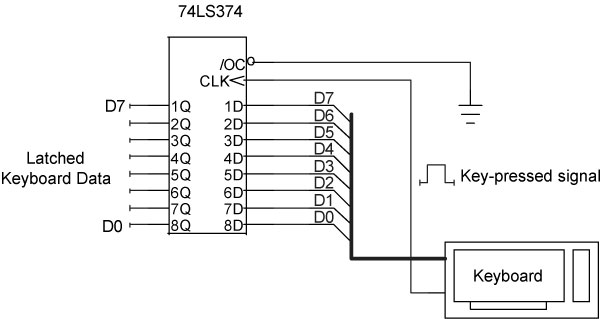
A keyboard, for example, may produce a “key-pressed” signal that indicates to external circuitry that the keyboards output lines contain new information. A 74LS374 latch circuit (Figure 3-10) can use the key-pressed signal to latch information and hold it so a computer can access it through an input port. The latch circuit makes the keyboard data available even after an operator releases a key.
This circuit will let the computer obtain keyboard data from an input port after a user presses a key, but this scheme has a problem. Suppose the operator presses the “2” key five times in sequence and expects the attached computer to receive five 2s in a row. Each time the operator presses the “2” key, the keyboard produces the same code,
001100102 for an ASCII 2, and the latch grabs it.
Figure 3-10
A 74LS374 latch circuit stores 8-bit data from a keyboard when it received a key-pressed signal. When the user releases a key, the keys code remains available at the latchs outputs.
But to an observer looking only at the latch outputs, the code doesnt change. (The keyboard does not reset the latch between key presses.) Each update of the latch from another push of the “2” keys simply leaves the same code, 001100102, on the latch outputs. So the computer cannot distinguish one 2 from any of the others. And because the latch retains the data, the computer could continue to input “old” data even though no one has pressed any other keys. Obviously, the computer and the keyboard need a way to synchronize their operations. An additional circuit element, called a flag, lets the keyboard circuit tell the computer, “I have new data.” In effect, a flag works like this:
- The keyboard latches new data and raises a flag.
- The computer regularly checks the flag.
- If the computer sees the flag is “up”, it reads the keyboards data and then pulls the flag “down.”
If the computers software checks the flag and finds it down, the software knows the keyboard has no new information, and it continues to its next task. This sort of arrangement lets the computer accept a series of five 2s from the keyboard. Each press of the “2” key raises the flag, signaling the computer to get the new data and then clear the flag so its ready for the next keyboard operation.
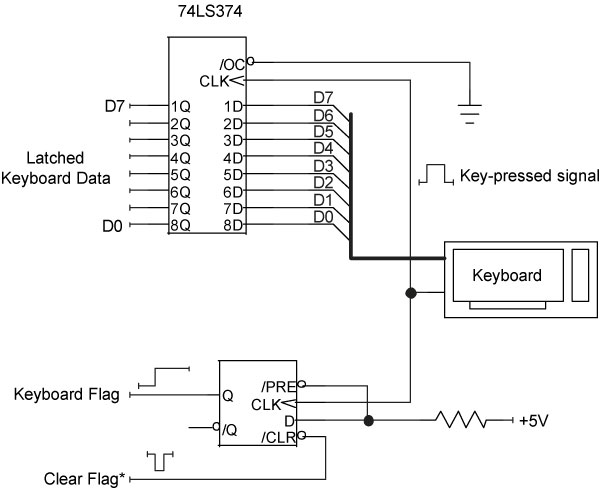
Figure 3-11 includes a flip-flop circuit that serves as a flag. The flip-flop works like a 1-bit memory. It transfers the state of the D input to the Q output during the logic-0 to logic-1 (positive-going) edge of the signal applied to the flip-flops clock (CLK) input. In this case, the circuit designers have connected the D input to +5V or logic 1. The CLK signal comes from the keyboards key-pressed signal, the same signal that latches the keyboard data. When the flip-flop receives the CLK signal, the logic 1 at the D input gets transferred to the Q output, which provides the flag signal to the computer. A logic 0 at the Q output indicates no keyboard data, while a logic 1 tells the computer the latch has new keyboard data.
Figure 3-11
A D-type flip flop serves as a flag that lets a computer know a keyboard has new data available. The computer clears the flag after it gets the keyboards new information.
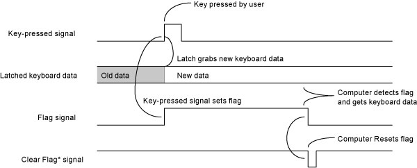
As part of a flag-detecting sequence, the software must clear the flag. The flip-flop provides a clear input (/CLR) that resets the Q output to a logic 0 state, thus clearing, or “lowering,” the flag. A logic 0 on the /CLR input clears the flip-flop back to the Q=0 state. The timing diagram in Figure 3-12 shows the sequence of events.
Figure 3-12
The keyboard timing starts when a user presses a key. The key-pressed signal latches new data and sets the flag. After the computer detects a set flag, it grabs the keyboards data and resets the flag for the next keystroke.
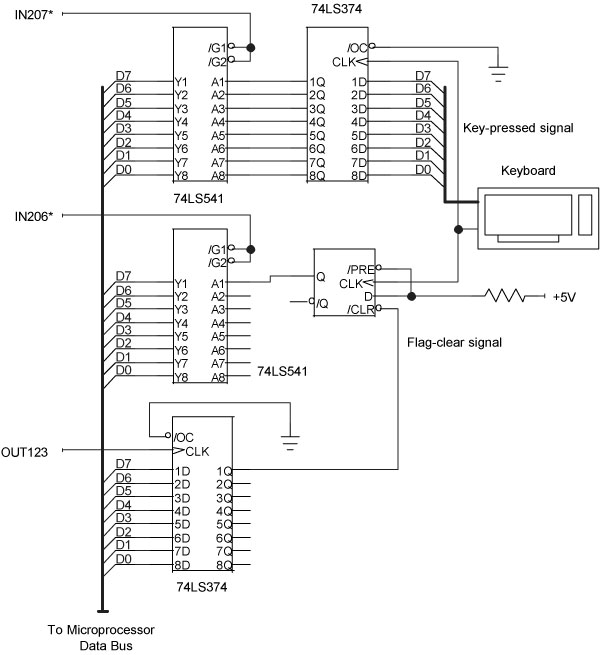
You may wonder how the computer detects the flag signal. The circuit designers connect the flip-flops Q output to a TTL-compatible input-port line so the computer can monitor its state. The signal to clear the flag comes from an output port. A complete keyboard interface circuit (Figure 3-13) uses an 8-bit input port (207) for the keyboard data, one bit on an input port (206) for the keyboard flag, and one bit on an output port (123) to clear the flag. The software must check the keyboard flag regularly to determine when the keyboard latch has new information.
Figure 3-13
A complete keyboard circuit includes an input port for the keyboard data, an input port for flags, and an output port to clear flags. The latter two ports may connect to additional flags for other I/O devices.
Although using flags to indicate external activities and putting an application program in a continuous flag-checking loop makes sense in some situations, it can needlessly tie up the computer and can chew up valuable processing time. In Visual Basic, for example, you can use the Timer control to govern reading and testing of external flags. Although Visual Basic provides clock divisions of 1 millisecond, in practice the clock produces intervals of about 1/18th second. This rate for checking flags should suffice in many applications.
Put it all together
Now the keyboard circuit needs software to test and reset the flag and to get data. Assume the flag input port (206) also connects to flags from other devices. To keep a design such as that shown in Figure 3-13 easy to debug and document, we suggest you use the same bit position for a flag and its associated flag-clear signal. Thus, in the keyboard example, the flag appears at input-port bit D7, and at output port (123), bit D7 clears that flag.
In the following example, when the software detects any set flag at input port 206, it checks the flag bits in sequence, starting with D7 and ending with D0. This establishes a built-in priority in servicing devices. So, if you have a device that requires fast service, make its flag the first one checked (D7).
The following software does not maintain an output-port status byte for the port used to clear the flags. We assumed a normal output state of 111111112 for this port. The software will force an individual bit to logic 0 for a few microseconds to clear a corresponding flag bit, and then restore the bit to logic 1.
'Establish mask bytes See Chapter 2 | ||
Dim | D7_1 | As Byte |
Dim | D6_1 | As Byte |
'etc... | ||
'Establish mask-byte values See Chapter 2 | ||
D7_1 | = &H80 | '10000000 |
D6_1 | = &H40 | '01000000 |
'etc... | ||
'Establish byte variables | ||
Dim | clear_all_flags | As Byte |
Dim | normal_all_flags | As Byte |
Dim | keyboard_input_port | As Integer |
Dim | flag_input_port | As Integer |
Dim | flag_clear_port | As Integer |
Dim | flag_status | As Byte |
Dim | D7_flag_clear | As Byte |
Dim | D6_flag_clear | As Byte |
Dim | D5_flag_clear | As Byte |
Dim | D4_flag_clear | As Byte |
Dim | D3_flag_clear | As Byte |
Dim | D2_flag_clear | As Byte |
Dim | D1_flag_clear | As Byte |
Dim | D0_flag_clear | As Byte |
'Define flag-clearing bit patterns | |||
clear_all_flags | = | 0 | '00000000 |
normal_all_flags | = | 255 | '11111111 |
D7_flag_clear | = | 127 | '01111111 |
D6_flag_clear | = | 191 | '10111111 |
D5_flag_clear | = | 223 | '11011111 |
D4_flag_clear | = | 239 | '11101111 |
D3_flag_clear | = | 247 | '11110111 |
D2_flag_clear | = | 251 | '11111011 |
D1_flag_clear | = | 253 | '11111101 |
D0_flag_clear | = | 254 | '11111110 |
'Define I/O port addresses | |||
keyboard_input_port | = | 207 | |
flag_input_port | = | 206 | |
flag_clear_port | = | 123 | |
'First clear all flags to initialize the system |
'Set all flag-clear signals to logic 0 |
'Then reset all flag-clear signals logic 1 to make flags ready |
outportb(flag_clear_port, clear_all_flags) |
outportb(flag_clear_port, normal_all_flags) |
'Main flag-checking routine... |
'Get all flag bits |
flag_status = inportb(flag_input_port) |
'Any flags set? If so, check individual flags | ||
If flag_status >0 | ||
Then | ||
'Check flag at D7, highest priority = keyboard | ||
If (flag_status AND D7_1 >0) | ||
Then | ||
'Get the keyboard port's data | ||
port_data = inportb(keyboard_input_port) | ||
'...other processing steps go here | ||
'Clear the associated keyboard flag | ||
outportb(flag_clear_port, D7_flag_clear) | ||
outportb(flag_clear_port, normal_all_flags) | ||
End If | ||
'Check flag at D6, next highest priority | ||
If (flag_status AND D6_1 >0) | ||
Then | ||
'Get the input port's data | ||
some_data = inportb(some_port) | ||
'Clear the associated flag | ||
outportb(flag_clear_port, D6_flag_clear) | ||
outportb(flag_clear_port, normal_all_flags) | ||
'...other processing steps go here | ||
End If | ||
...and so on for the remaining six flags | ||
End If | ||
Note that the test of individual flags checked for >0, rather than for a specific value. You can use either technique.
Routines can check for individual flags, too. You dont need to check all eight flags at an input port unless your interface circuits have implemented them. And at times, you will want to monitor some flags more often than others.
A final note about I/O ports
In Chapter 2, a section explained that programmers should maintain a “status byte” for every output port so they can determine the state of the outputs at any time. Some output ports, typically those on I/O cards or built into electronic devices, may provide access to that information through a built-in input port (Figure 3-14). The input port simply reads the bits from the port’s output lines. Software can use this information instead of saving a status byte. For clarity, the following example uses values in the port-control statements:
outportb(117, control_byte) |
port_status = inportb(117) |
Figure 3-14
Some output ports provide a means to read the state of the associated output lines. The ports shown in this example actually exist within one IC or device.
You still might want to maintain information in a status byte, though. In most cases, it requires less time to get status information from a byte of stored data than to retrieve data from an input port. So, if you have software that requires careful timing, use a status byte. Software control of I/O ports in many PCs is not deterministic. That means you cannot tell exactly how long it will take for an I/O operation to take place after a computer receives a port-control command.
Maintaining status bytes also simplifies debugging and testing. When you debug software, you may have to do so without any connected I/O devices. So, if you rely on an output port with an associated input port to maintain port-status information, you may not have access to the port information until designers have configured and attached the I/O ports. Also, during testing, you may need to compare port operations with variables you track using special “watch” windows in your development-software suite; Visual Basic, C, C++, and so on. If the hardware has problems, it may corrupt, or make unavailable, any data from an output port’s built-in input port. So, by maintaining the output port’s status information in a variable, you at least know what state the port is supposed to be in.
For more information
We hope you found the Chapter 3 informative. To go back to the Main Page, click here.
You can purchase the complete Digital I/O Handbook for only $19.95 by clicking here. The Digital I/O Handbook is FREE with any qualifying Sealevel Digital I/O product purchase.
