
WinSSD Software Utility Overview
WinSSD® Serial Diagnostic Utility
WinSSD is a full-featured synchronous/asynchronous diagnostic utility for Microsoft Windows operating systems. For asynchronous serial devices, WinSSD allows the user to modify the default UART parameters, perform external loopback tests, toggle modem control signals, perform simple BERT tests and includes terminal mode emulation. When used with a Sealevel synchronous serial adapter, the user has full control over electrical interface, framing method, RSET and TSET source, transmitter and receiver bitrate, oscillator frequency, CRC, preamble, clock encoding, sync character and more.
WinSSD is available as a standalone utility and is included with Sealevel’s SeaCOM, SeaLINK and SeaMAC software suites.
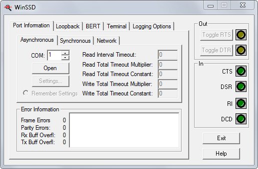
Port Information
The WinSSD Port Information tab allows the user to select whether they are communicating over asynchronous COM ports, synchronous ports or Ethernet Network ports.
The modem control signals, displayed on the right side of each WinSSD screen, allow the user to control outputs and monitor inputs.
Any errors received during communication are displayed in the Error Information box.
WinSSD Asynchronous Serial Interface
This tab allows the user to select the COM port to communicate with and provides a context sensitive ‘Settings’ button to configure the port once you have opened it. To initiate a Loopback or BERT test, select the appropriate COM port and click the ‘Open’ button. Then select the Loopback or BERT tab to configure the test settings and initiate a test. When using SeaLINK Ethernet serial drivers to map a device’s port to a COM port, the COM port selection should be used to open the port.
Once the asynchronous COM port has been opened, click the ‘Settings…’ button to bring up the WinSSD Asynchronous Port Settings screen that allows configuration of communications parameters.
WinSSD Synchronous Serial Interface
This tab allows the user to select the synchronous SeaMAC device to communicate with and provides a context sensitive ‘Settings’ button to configure the device once you have opened it. To initiate a BERT test, select the appropriate SeaMAC device number and click the ‘Open’ button. Then select the ‘Settings’ button to configure the communications parameters. Then select the BERT tab or Terminal tab to initiate a test. The Loopback tab is not recommended for synchronous communications because it sends one character at a time which is invalid in most synchronous protocols.
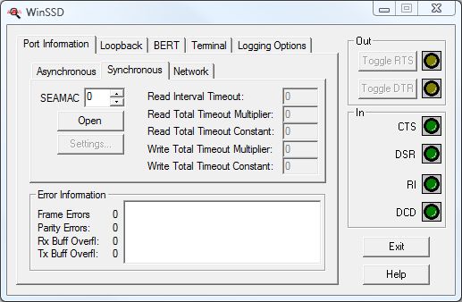
Once the synchronous device has been opened, click the ‘Settings…’ button to bring up the WinSSD Synchronous Port Settings screen that allows configuration of communications parameters.
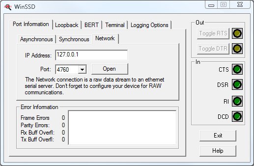
WinSSD Ethernet Network Interface
This tab is only applicable to Sealevel <SeaLINK Ethernet Serial Servers>. Using this feature will bypass the SeaLINK driver. If use of the COM port is desired, the Asynchronous tab should be used. Selecting the Network tab under the Port Information tab allows you to specify the IP address and Port Number of the Ethernet serial server that you want to communicate with. The Ethernet serial server must be configured for RAW communications. Click the ‘Open’ button to establish communications. Any communication errors are displayed in the Error Information section of the screen.
Select the Loopback, BERT, or Terminal tab to continue testing the Ethernet serial server.
WinSSD Loopback Test
WinSSD’s Loopback tab allows functional testing of any serial port on the system, provided a loopback plug is connected to the serial port. Sealevel offers prebuilt loopback plugs for testing data communications on DB9 (LB101) and DB25 (LB102) serial ports. The ‘Diagrams’ button provides detailed information for building loopback plugs for supported electrical interfaces, required for testing modem control signals. The loopback test includes a Pattern Test, ASCII Test and Modem Control Test. Multiple passes can be programmed for each test if required.
Note: Because of the nature of synchronous communications and the fact that the Loopback tab sends data one byte at a time, this test is not recommended for use with our SeaMAC synchronous serial driver.

Pattern Test — Check the ‘Pattern Test’ check box to enable this test. The Pattern Test sends the alternating hexadecimal bit patterns 0xAA and 0x55. You can change the number of times the test is run by changing the number of passes in the box to the right. To prevent this test from running, uncheck the box.
ASCII Test — Check the ‘ASCII Test’ check box to enable this test. The ASCII Test sends “The quick brown fox jumps over the lazy dog”. To allow this test to run, chech the ASCII Text box. You can change the number of times the test is run by changing the number of passes in the box to the right. To prevent this test from running, uncheck the box.
Modem Control Test — Check the ‘Modem Control Test’ check box to enable this test. The Modem Control Test assumes you have a loopback that has the output signal RTS connected to the input signals CTS and RI. It also assumes you have the output signal DTR connected to the input signals DSR and DCD. You can change the number of times the test is run by changing the number of passes in the box to the right. To prevent this test from running, uncheck the box.
Diagrams — The ‘Diagrams’ button provides detailed information for building loopback plugs. It includes pin outs for DB9F and DB25F connectors as well as full modem control signals for RS-232, RS-422, RS-485 and RS-530/530a.
WinSSD BERT (Bit Error Rate Test)
The BERT tab provides a multithreaded bit error rate test that is used to verify the operation and performance of a serial port. BERT can be used in a loopback or point-to-point test configuration. The test tracks bit errors and sync losses while displaying transmit and receive frame counts, the number of bytes verified and driver error statistics. The transmit and receive data rates are useful for throughput monitoring. The size of the transmit frame can be selected using the drop box.

Bit Error Rate Test — WinSSD BERT transmits and receives the standard 511-bit BERT pattern defined in the ITU standard O.153. The format is called 2**9-1. Because a frame is required to be a multiple of 8-bits, we send the 511-bit pattern back-to-back eight times to create a 511-byte pattern.
All of the numbers, except data rate fields, are simply counters for each event. Bit errors represent how many bits are wrong in the received pattern up to the point of a sync loss. A sync loss happens when there are more than three consecutive bytes of bad data. WinSSD will then try to regain sync with the incoming pattern.
The Tx Data Rate and Rx Data Rate are calculated values based on how many frames are sent in a given time interval. The values may fluctuate because a partial frame may not be included in the specific time interval.
Sync Status is red if there is no incoming data. Yellow signifies that data is being received but no sync is established. Green signifies that data is being received and sync is established.
Test Time — This is the elapsed time WinSSD has been on the BERT screen once a test has been started. Close the serial port to stop the timer.
Reset Stats — The ‘Reset Stats’ button clears all counters.
WinSSD Terminal
The Terminal tab provides a basic terminal interface to your equipment without requiring a separate terminal emulation program. Everything you type in the large window will be sent across the open serial port. Any data received from the serial port will also be displayed in this window. If you want to send data as a string instead of character-by-character, type your text in the smaller window and click the ‘Send’ button. To allow you to communicate with devices that communicate in non-ASCII text modes, click the ‘Options’ button and select the option of displaying the incoming data as normal ASCII text, two-digit Hex values or as a split screen with ASCII text on the left side with corresponding Hex values on the right side.

Search — The ‘Search’ button allows you to search for strings in the received serial data.
Clear — The ‘Clear’ button clears the screen.
WinSSD Logging Options
WinSSD can log serial data from the BERT tab and from the Terminal tab to a file during operation. You can run multiple simultaneous copies of WinSSD, each creating unique log files. WinSSD creates a continuous file that can grow to considerable size if left logging data for extended periods. Extended data logging sessions can impact WinSSD performance due to the extra overhead required for logging information.

BERT Logging Options — The check boxes allow you to select the information to be written to the log file. This information is written to the log file when you select the BERT tab and click the Start button.
Terminal Logging Options — The check boxes allow you to select the information to be written to the log file. This information is written to the log file when you select the Terminal tab and data is being transmitted or received.
General — If you want general ‘Port Error Messages’ included in the log file, check this box.
WinSSD Modem Control
On the right side of each screen are buttons that allow you to toggle (active or inactive) the RTS and DTR output signals. The state of the incoming CTS, DSR, RI, and DCD signals are also displayed.

Port Settings -> WinSSD Asynchronous Ports Settings
On the Port Information tab, selecting the Asynchronous tab and clicking the ‘Settings’ button brings up the SeaCOM Port Settings screen that allows you to completely configure an asynchronous serial port.
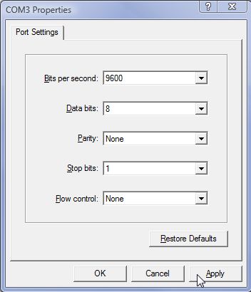
Bits Per Second — This allows the selection of the data rate in Bits Per Second (or Baud) at which the port will operate.
Data Bits — This allows the selection of 5, 6, 7 or 8 data bits per character.
Parity — This allows the selection of the parity associated with each transmitted character. Valid options are None, Odd, Even, Mark and Space.
Stop Bits — This allows the selection of 1, 1.5 or 2 stop bits per character.
Flow Control — This allows the selection of None, Xon/Xoff or Hardware.
Port Settings ->WinSSD Synchronous Ports Settings
On the Port Information tab, selecting the Synchronous tab and clicking the ‘Settings’ button brings up the SeaMAC Configuration Utility that allows you to completely configure a synchronous serial port. This window allows you to configure all available parameters and optionally save the settings as the default for the SeaMAC synchronous serial driver.

Electrical Interface — This allows the selection of the <electrical interface> and voltage levels that will be present on the synchronous serial port.
Framing — Sealevel synchronous serial devices provide support for SDLC/HDLC, asynchronous, isochronous, monosync., bisync and RAW (bit shifter) modes. Select the appropriate framing method here.
Clock Encoding Method — If there is a separate clock provided with the data, you should select “ssiClockEncodingNone”. You also have the option to encode the clock on the data signal. While this significantly limits the data rate, it allows sending and receiving a single data stream. The supported encoding methods are based on the communications chip used on the Sealevel synchronous device.
SDLC Address Mode — SDLC/HDLC supports supplying the address of the receiver. If you enable this option, you can specify your address in the SDLC Address Character box and only receive messages addressed to this station.
SDLC Flags Share Zero — An SDLC flag is a binary sequence of 01111110. If you are idling flags, you would transmit 01111110 01111110. You can allow the hardware to combine the two consecutive 00 bits into one. The resulting flag sequence would be 011111101111110. Enable this selection if the hardware you are communicating with requires it.
RxTimingSource / TxTimingSource — If you are receiving an external clock or are generating the clock internally, you inform the driver based on the values in these fields. ssiTimingBrg’ indicates you are using your internal Baud Rate Generator (BRG) to drive that function. If you are receiving the clock on the RXC DB25 pin(s), set the field to ssiTimingRset. If you are receiving the clock on the TXC DB25 pin(s), set the field to ssiTimingTset.
If you have an encoded clock, set both of these fields to ssiTimingDpll to indicate the Digital Phase Lock Loop (DPLL) will be used to recover the clock from the incoming data stream.
Tset Direction — If you are generating a clock then you need to output the clock on the TSET pin(s) on the connector and set this field to Output. If you are receiving a clock, set this to Input and the received clock signal on the TXC pin(s) will be turned around and output on the TSET pin(s).
DPLL Source — Normally the DPLL will get its clocking input from the internal BRG. It is possible to feed an external clock into the RXC pin(s) on the connector. This field selects which source to use.
PreTxDelay / PostTxDelay — If you are using two-wire RS-485, you can turn on the transmitter early to allow additional flags to be sent for synchronization. Specify the number of milliseconds you want the transmitter turned on early in the PreTxDelay field. If you want to keep the transmitter on after the closing flag, set the number of milliseconds in the PostTxDelay field.
CRC Preset — The Cyclic Redundance Check (CRC) generator can be seeded with either 0x0000 or 0xFFFF. Select which CRC to use in this field.
CRC Polynomial — Select ssiCrcCcitt to enable the normal SDLC/HDLC CCITT CRC. If you are not using SDLC/HDLC, you shold set this to ssiCrcNone since the SeaMAC driver only uses the CRC in SDLC/HDLC mode.
Sync Character Size — If you have Framing set to ssiCharacterSync, select whether you want monosync or bisync using this field. A value of 8 indicates using a 1-character sync byte (monosync). A value of 16 indicates using a 2-character sync byte (bisync). If you set Framing to ssiFramingRaw, set this field to 0 to indicate there is no sync character.
Sync Character — If you specify a value of either 8 or 16 for Sync Character Size, specify the sync character here.
Stop Bits / Parity — Set the Stop and Parity bits for asynchronous mode only.
Idle Mode — This selects what is sent out on the data line when the driver has nothing else to send. The possible values are determined by the communication chip used on the Sealevel synchronous device.
Internal Loopback — In normal operation this is set to Off. If you need test the device without using a loopback, set this to On. The transceiver chips are not tested in this mode.
Oscillator Frequency — This number represents the actual oscillator value on Sealevel synchronous device. If you ordered the synchronous device with a special oscillator, set the correct value in this field. This field tells the SeaMAC driver the oscillator value to use for calculating the correct data rate.
Bit Rate — This is the actual data rate, in Bits Per Second (or Baud), that you want the Sealevel synchronous device to operate.
BRG Source — By default, the BRG source is set to Internal Source. In the rare case where you are feeding a signal into the RXC pin(s) instead of using the internal oscillator, use this field to inform the SeaMAC driver.
Preamble Pattern — If you have a Sealevel Synchronous serial device based on the Zilog Z16C32, you can select different patterns that will be transmitted before the opening flag in SDLC/HDLC mode. Only used in rare circumstances.
Preamble Length — The preamble patterns specified in the Preamble Pattern field are variable length in multiples of 8-bits. This field allows you to specify how many times the pattern is sent before the opening flag. Only used in rare circumstances.
Options — Auto Calculate Timeout — Checking this field tells the driver to calculate reasonable timeout values based on the data rate. Uncheck this box to manually select your own values.
Options — Auto RTS RS-485 — If you have the electrical mode set to RS-485 or RS-485T and you want the driver to automatically control tri-stating the transmitter, check this box. If you do not check this box, you have to manually control tri-stating the transmitter using the RTS button.
Options — 485 Echo Suppression — If you are in two-wire RS-485, everything you transmit will be received ahead of the response from the device. Check this box to suppress the echo. The receiver will be disabled while the device is transmitting.
Save Configuration Button — This causes the SeaMAC driver to store these settings in the system registry. The next time you open the device, these values will be read back as the default.
Set Configuration Button — This causes the SeaMAC driver to load the specified values into the hardware registers on the Sealevel synchronous device. These values will be lost and reset back to the default settings when the port is closed.
Categories: